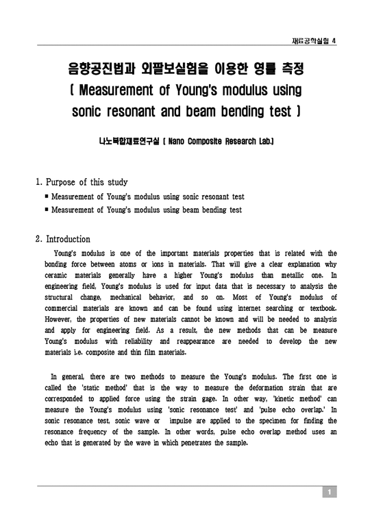
[재료공학실험] 음향공진법과 외팔보실험을 이용한 영률 측정 예비보고서
 등록일 / 수정일
 페이지 / 형식
 자료평가
자료평가 구매가격
구매가격
- 2009.04.24 / 2019.12.24
- 7페이지 /
 hwp (아래아한글2002)
 - 평가한 분이 없습니다. (구매금액의 3%지급)
- 800원
최대 20페이지까지 미리보기 서비스를 제공합니다.
자료평가하면 구매금액의 3%지급!
 1
1 2
2 3
3 4
4 5
5 6
6 7
7
추천 연관자료
- 목차
-
1. Purpose of this study
2. Introduction
2-1-1. Measurement of Young's modulus using sonic resonance
2-1-2. Sonic resonant test method (ASTM C848-78)
2-1-3. Calculation of Young's modulus and shear modulus
2-2-1. Measurement of Young's modulus using beam bending test
3. Experimental equipment
3-1. Measurement of Young's modulus using sonic resonant test
3-2. Measurement of Young's modulus using beam bending test
4. 실험 예비 문제
5. References
- 본문내용
-
나노복합재료연구실 ( Nano Composite Research Lab.)
1. Purpose of this study
■ Measurement of Young's modulus using sonic resonant test
■ Measurement of Young's modulus using beam bending test
2. Introduction
Young's modulus is one of the important materials properties that is related with the bonding force between atoms or ions in materials. That will give a clear explanation why ceramic materials generally have a higher Young's modulus than metallic one. In engineering field, Young's modulus is used for input data that is necessary to analysis the structural change, mechanical behavior, and so on. Most of Young's modulus of commercial materials are known and can be found using internet searching or textbook. However, the properties of new materials cannot be known and will be needed to analysis and apply for engineering field. As a result, the new methods that can be measure Young's modulus with reliability and reappearance are needed to develop the new materials i.e. composite and thin film materials.
In general, there are two methods to measure the Young's modulus. The first one is called the 'static method' that is the way to measure the deformation strain that are corresponded to applied force using the strain gage. In other way, 'kinetic method' can measure the Young's modulus using 'sonic resonance test' and 'pulse echo overlap.' In sonic resonance test, sonic wave or impulse are applied to the specimen for finding the resonance frequency of the sample. In other words, pulse echo overlap method uses an echo that is generated by the wave in which penetrates the sample.
2-1-1. Measurement of Young's modulus using sonic resonance
The principal idea behind the sonic resonance test method can be explained using the equation by which one can measure the propagating speed of flexural sonic wave through a medium
(1)
where v is the propagating speed of the flexural wave on a string, F is the tension applied to both sides of the string, P is the mass per unit length of the string.
Some methmatical manipulation of Eq (1) yields
- 참고문헌
-
1) G. Pickett, Amer. Sco. Testing. Mater. Proc. 45, (1945) 864
2) S. Spiner, T.W. Reivhard, and W.E. Tefft, J. Res. Nat. Bur. Stand. 16A, (1960) 147
3) Mechanical Metallurgy, SI Metric Edition, George E. Dieter, McGraw Hill
4). Physical Metallurgy Principles, 3rd edition, Reed-Hill, PWS-KENT
자료평가
-
아직 평가한 내용이 없습니다.


